Taunton Motors
Choosing the right Electric Gear Box is not a catalog exercise. It is a decision about torque, speed, duty cycle, safety, and long-term operating cost. A gearbox that looks suitable on paper may overheat beside a conveyor, stall under repeated starts, or wear quickly in dusty conditions. Real equipment tells the fuller story. Motor size matters, but so do load inertia, shock loads, mounting position, ambient temperature, and available maintenance access.
A practical selection begins with verified operating data. Measure required output torque, target speed, service hours, and starting frequency. Then compare gearbox ratios, efficiency ratings, backlash, noise levels, and thermal capacity. Check whether the housing, seals, and lubrication system match the environment. Food-processing areas, outdoor platforms, and washdown zones demand different protection. Manufacturer datasheets provide useful limits, yet independent testing, installation records, and experienced technician feedback can reveal weaknesses.
Do not choose by price alone. The cheapest unit may consume more energy or require earlier replacement. A larger model is not automatically safer, either; it can create excess cost, poor efficiency, and difficult alignment. Technicians often see selection errors begin with one missing detail: a peak load mistaken for a normal load. That mistake deserves attention. This guide explains how to compare specifications, question supplier claims, and validate the final choice through calculations and site conditions. When uncertainty remains, ask a qualified engineer to review the application before purchase. Reliable decisions are measured in quiet operation, stable output, and predictable service.
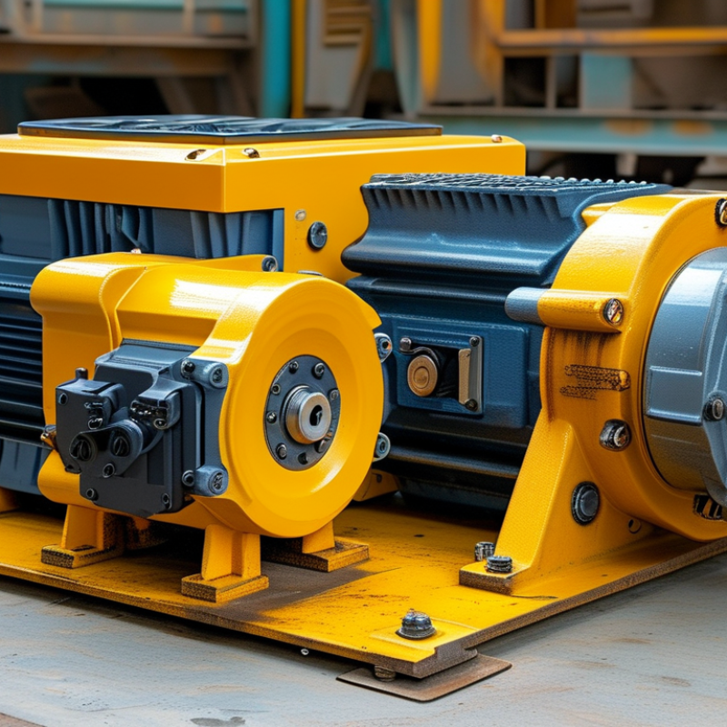
An electric gear box combines an electric motor with a mechanical gear train. The motor creates rotational energy, while the gears adjust speed and torque. A high-speed motor may turn several thousand times per minute. The gearbox reduces that speed and delivers stronger rotation to the output shaft.
Inside the housing, gears transfer motion through different sizes and tooth arrangements. A larger output gear turns more slowly, but it produces greater torque. Bearings support the shafts and reduce friction. Lubricant protects the teeth from heat and wear. A controller can also regulate motor speed, direction, and starting force. In practice, smooth operation depends on more than the motor rating. Load weight, duty cycle, shaft alignment, and available space all matter.
Choose a gear ratio based on the machine’s real workload, not only its advertised power. For example, a conveyor carrying 80 kilograms may need steady torque during startup. Check the output speed, rated torque, mounting position, voltage, and protection level. Listen for clicking, grinding, or uneven vibration during testing. These sounds often reveal alignment or lubrication problems early. Keep a maintenance record.
Small details matter.
I have seen selection mistakes caused by ignoring peak loads. A gearbox may run well for ten minutes, then overheat during repeated starts. Allow a practical safety margin, but avoid excessive sizing. An oversized unit can waste energy and increase cost. The correct choice balances performance, service life, and the conditions around the machine.
How to Choose the Right Electric Gear Box?
Which Operating Requirements Should You Define First?
Before comparing an electric gear box, define the real operating load. Record continuous torque, peak torque, output speed, and acceleration time. Include how often the unit starts, stops, reverses, or runs intermittently. A conveyor moving 80 kilograms may need modest torque during operation, but much more during startup. I have seen selections fail because teams measured running load only. The first estimate is often wrong.
Environment matters just as much. Note ambient temperature, dust, moisture, vibration, installation angle, and available space. Confirm the motor voltage, control method, mounting arrangement, shaft position, and allowable noise level. If the gearbox must hold a load safely, specify the required holding torque and braking behavior. These details should be checked against technical data and applicable safety requirements, not assumed from a similar machine.
Tips: Write a simple duty profile. Include load, speed, operating hours, starts per hour, and peak events. Leave a realistic service margin, but avoid excessive oversizing. An oversized unit may increase cost, inertia, and energy use. Ask the supplier for efficiency curves, thermal limits, backlash values, and service instructions. Then review the choice with maintenance staff. They may notice an access problem that a design drawing hides. I still recommend testing uncertain assumptions with a prototype or measured field data.
Define output torque, output speed, and duty cycle first. These operating requirements establish the basic gearbox size and transmission ratio before environmental factors such as temperature, ingress protection, mounting position, and service life are checked. The values below are representative engineering design points, not brand ratings.
Matching torque, speed, and gear ratio starts with the driven machine, not the motor. Record the required output speed, continuous torque, peak torque, and daily operating hours. For a conveyor moving 30 rpm, a 1,500 rpm motor needs an approximate 50:1 reduction ratio. The basic power relationship is T = 9,550P/n, where torque is measured in newton-metres, power in kilowatts, and speed in revolutions per minute. This calculation is useful, but it is not enough.
The U.S. Department of Energy’s 2021 Motor Systems Market Assessment reports that motor systems consume about 69% of industrial electricity in the United States. Small sizing errors can therefore create lasting energy losses. Choose a gearbox with a rated output torque above the calculated load. Include a service factor for starts, shocks, reversing, and uneven loading. A dusty packaging line may need more protection than a clean laboratory machine. Check the gearbox efficiency at the actual ratio, not only its advertised maximum.
Speed matching also requires attention to motor slip and control settings. A nominal 1,500 rpm motor may run slightly slower under load. I have seen selections fail because designers used no-load speed. That mistake is easy to repeat. Confirm thermal capacity, shaft loads, mounting position, and backlash before ordering. IEC 60034-30-1 provides efficiency-class guidance for motors, while ISO 6336 offers calculation methods for cylindrical gear strength. These standards improve confidence, but real duty cycles still deserve a practical review.
Choosing an electric gearbox starts with the driven machine, not the motor alone. Compare planetary, helical, worm, and bevel designs by torque, speed ratio, efficiency, and installation space. Planetary units suit high torque in compact spaces. Helical gearboxes usually offer strong efficiency and steady operation. Worm gearboxes can provide large reductions, but sliding contact may create more heat. Bevel designs help when shafts meet at an angle.
Materials change performance more than many catalog tables suggest. Hardened steel gears resist repeated loads and tooth wear. Cast iron housings absorb vibration, while aluminum reduces weight and may cool quickly. However, lighter construction can flex under shock loads. Stainless steel helps in wet or corrosive environments, though it often costs more. Check gear hardness, housing thickness, bearing type, and sealing method together.
I have found that real operating conditions expose weak comparisons. A gearbox rated for 500 newton-metres may fail early under frequent starts, impact loads, or poor alignment. Noise matters. Measure twice. Compare service factors, thermal limits, backlash, maintenance access, and documented test methods. My early comparisons were too neat; I trusted maximum torque and ignored duty cycles. That mistake can produce a gearbox that looks suitable on paper but overheats beside the machine. Ask for measured efficiency at your actual speed, not only a peak value. Examine the mounting surface and shaft load requirements before approving the design.
A practical comparison of common gearbox designs, performance characteristics, and material choices for electric-drive applications
| Comparison Dimension | Spur Gearbox | Helical Gearbox | Bevel Gearbox | Worm Gearbox | Planetary Gearbox |
|---|---|---|---|---|---|
| Typical Application | Simple conveyors, small mechanisms, instruments, and low-cost electric drives | Industrial conveyors, mixers, pumps, machine tools, and general motion systems | Right-angle drives, lifting equipment, conveyors, and compact transmission layouts | Hoists, gates, positioning systems, and applications requiring high reduction in a compact arrangement | Robotics, servo systems, automation, mobile equipment, and high-torque compact drives |
| Typical Efficiency | Approximately 94–98% per gear stage | Approximately 95–98% per gear stage | Approximately 94–98% per gear stage | Approximately 50–90%, depending strongly on reduction ratio, lubrication, and lead angle | Approximately 94–98% per planetary stage |
| Typical Ratio Range | About 1:1 to 6:1 per stage; higher ratios usually require multiple stages | About 1.5:1 to 10:1 per stage; multiple stages provide higher total ratios | About 1.5:1 to 5:1 per stage; commonly used for a 90-degree direction change | About 5:1 to 100:1 in one stage, depending on design and lead angle | About 3:1 to 10:1 per stage; multiple stages can provide ratios above 100:1 |
| Torque Density | Low to moderate; suitable for relatively light and moderate loads | Moderate to high; improved tooth contact supports higher loads than spur gears of similar size | Moderate to high; suitable for transmitting torque through a right-angle arrangement | Moderate; high reduction is possible, but heat generation can limit continuous output torque | High; load is shared among multiple planet gears, producing strong torque capacity for its size |
| Backlash and Positioning | Moderate backlash; economical versions are not ideal for precision positioning | Low to moderate backlash; precision versions can support accurate motion control | Moderate backlash; precision depends on tooth quality, bearing arrangement, and adjustment | Low apparent backlash is possible, but friction and elastic deformation affect positioning accuracy | Low backlash options are widely available and well suited to servo positioning |
| Noise and Vibration | Higher noise at high speed because teeth engage suddenly | Generally quieter and smoother because teeth engage gradually | Moderate noise; depends on spiral tooth geometry, speed, and manufacturing accuracy | Usually quiet at low and moderate speeds, but sliding friction can generate heat and noise | Low to moderate noise; balanced load sharing generally provides smooth operation |
| Axial Load | Very low axial force; primarily produces radial and tangential loads | Produces noticeable axial force; requires suitable thrust-bearing support | Produces axial and radial loads; bearing selection is important | Produces significant sliding and thrust loads; housing and bearing design are critical | Planetary gears can generate axial loads depending on the helical or spur configuration |
| Self-Locking Capability | No; the output can normally back-drive the input | No; a brake or holding mechanism is normally required for vertical loads | No; the output can normally back-drive the input | Possible at low lead angles, but self-locking is not guaranteed and should not replace a safety brake | No; a separate brake or holding mechanism is generally required |
| Common Gear Materials | Through-hardened alloy steel, stainless steel, or engineering plastics for light-duty loads | Case-hardened alloy steel, through-hardened steel, or nitrided steel | Case-hardened alloy steel or nitrided steel for demanding industrial applications | Hardened steel worm with bronze or specialized alloy-bronze worm wheel | Case-hardened alloy steel, nitrided steel, or hardened stainless steel for corrosion-sensitive applications |
| Common Housing Materials | Aluminum alloy for light weight; cast iron for higher stiffness and durability | Cast iron, ductile iron, or aluminum alloy depending on load and thermal requirements | Cast iron or aluminum alloy; steel housings may be used for severe-duty designs | Aluminum alloy for compact drives; cast iron for higher continuous load capacity | Machined steel, aluminum alloy, or cast iron depending on stiffness, weight, and precision requirements |
| Thermal Considerations | Generally low heat generation; cooling is usually straightforward | Good efficiency, but continuous high-speed operation may require thermal checking | Thermal performance is generally good when properly lubricated and sized | Most sensitive to heat because of sliding contact and lower efficiency; verify continuous thermal capacity | High efficiency, but compact construction can concentrate heat; confirm allowable continuous torque |
| Maintenance Requirements | Low to moderate; inspect lubrication, alignment, wear, and noise | Moderate; check lubricant condition, bearings, seals, and axial alignment | Moderate; inspect bearings, gear contact pattern, seals, and lubricant | Moderate to high; lubricant selection, temperature, wear, and backlash require close attention | Moderate; precision bearings, lubrication, seals, and backlash should be monitored |
| Best Selection Scenario | Choose when low cost, simple construction, and moderate speed are more important than quiet operation | Choose when efficiency, smooth running, and higher load capacity are required for parallel-shaft transmission | Choose when the motor and output shaft must be arranged at a right angle | Choose when a high reduction ratio and compact right-angle layout are needed, subject to thermal limits | Choose when high torque density, low backlash, compact size, and precision motion are priorities |
| Engineering Note | The listed values are representative engineering ranges rather than guaranteed ratings. Final selection should be based on motor power, output speed, continuous and peak torque, duty cycle, shock load, ambient temperature, mounting position, lubrication, allowable backlash, service life, and applicable safety requirements. | ||||
Choosing an electric gearbox starts with the installation environment, not only torque and speed. Check load direction, duty cycle, ambient temperature, and available space. A gearbox mounted on a flexible frame may vibrate, even when its rating looks sufficient. Use a rigid base, accurate shaft alignment, and a calibrated torque wrench. Keep cable glands tight and select an enclosure rating suited to dust or moisture.
Safety checks should happen before the first movement. Isolate electrical power, release stored energy, and verify zero voltage with a tested meter. Never rely on the control switch alone. Install suitable grounding, overload protection, thermal protection, and accessible emergency stopping equipment. Guards should cover couplings, shafts, and other rotating points. Limit switches also need testing under controlled conditions.
Maintenance is more than adding lubricant. Inspect oil leaks, unusual noise, rising temperature, loose fasteners, and cable damage. Record vibration and current readings during normal operation. Small changes can reveal bearing wear or misalignment early. Follow the service schedule and use compatible lubricants and replacement seals. A checklist helps, but it can miss changes between inspections. I once found a loose mounting bolt after a routine check, despite normal sound and temperature. That mistake reinforced the value of physical inspection, not just sensor data. Safety habits must remain practical. Test them at the machine.
: An electric gearbox combines an electric motor with mechanical gears. The motor creates rotation. The gears reduce speed and increase output torque. A high-speed motor may turn several thousand times per minute. The gearbox delivers slower, stronger rotation to the output shaft.
Different gear sizes transfer motion through the housing. A larger output gear turns more slowly. It also produces greater torque. Bearings support the shafts and reduce friction. Lubricant protects gear teeth from heat and wear.
Record continuous torque, peak torque, output speed, and acceleration time. Also record starts, stops, reversals, and operating hours. Include temperature, dust, moisture, vibration, and installation angle. Measure the available mounting space. The first estimate may be wrong.
Choose the ratio from the machine’s real workload. Do not rely only on advertised motor power. An 80-kilogram conveyor may need high torque during startup. Check output speed, rated torque, voltage, and protection level. Allow a practical safety margin.
Planetary designs provide high torque in compact spaces. Helical designs usually offer efficient, steady operation. Worm designs provide large reductions but may create more heat. Bevel designs suit machines with angled shafts. Space and duty cycle still matter.
Hardened steel gears resist repeated loads and tooth wear. Cast iron housings can absorb vibration. Aluminum housings reduce weight and may cool quickly. Stainless steel helps in wet or corrosive environments. Light materials may flex during shock loads.
Listen for clicking, grinding, or uneven vibration. These sounds may indicate poor alignment or weak lubrication. Check for overheating after repeated starts. A gearbox may run well for ten minutes, then overheat. Small details matter.
Yes, excessive sizing can increase cost, inertia, and energy use. An undersized unit may overheat or wear quickly. Compare thermal limits, efficiency, backlash, and service factors. Review shaft loads and mounting surfaces. My early comparisons were too neat.
Choosing the right Electric Gear Box begins with understanding how it converts motor speed into controlled mechanical output through gears, allowing equipment to achieve the required torque, speed, and motion. Before selecting a model, define the operating requirements, including load type, duty cycle, running time, ambient conditions, available space, noise limits, and power supply. These details establish the performance standards the system must meet.
Next, match the motor’s torque and speed to the desired output by selecting an appropriate gear ratio, while allowing sufficient capacity for starting loads and unexpected resistance. Compare gear box designs according to efficiency, backlash, durability, material strength, protection level, and application demands. Proper installation also requires accurate alignment, secure mounting, suitable lubrication, and correct electrical connections. Regular inspection, cleaning, temperature monitoring, and maintenance can extend service life. Finally, include safeguards such as overload protection, emergency stopping, guarding of moving parts, and compliance with relevant safety requirements to ensure reliable and safe operation.